
Forged monoblock
Review geometry and load requirements for a single-piece design.
Material / Geometry / Validation
Connect alloy wheel geometry, application loads and engineering evidence from the first conversation to the final specification.
Wheel families
Review geometry and load requirements for a single-piece design.
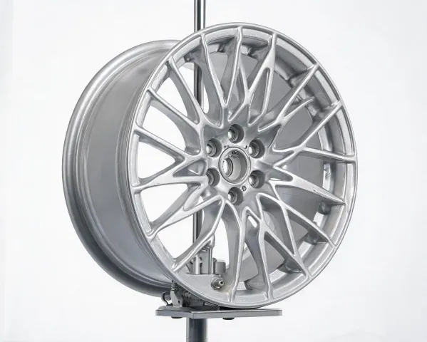
Consider casting geometry alongside the intended application and finish.

Evaluate spoke clearance and offset within the vehicle envelope.

Discuss assembly interfaces and dimensional boundaries.
Capture PCD, offset, center bore, brake clearance and the target load before a design is selected.
Define the test method, sample configuration and acceptance criteria for the intended duty cycle.
Keep drawings, revisions and market-specific requirements together for review.
Connect inspection records and change decisions to the applicable production lot.
Fastener interface
Wheel position
Duty boundary
Geometry control
Balance brake clearance and wheel geometry with the target application.
Define load, offset and intended road or off-road duty before selection.
Review unusual interfaces and validation needs against the platform brief.
Specifications
Validation
Installation
Share the interface, target market and duty cycle to begin a useful engineering conversation.